


Line and Load Reactors are used to protect motors and equipments by reducing the power line distortions, harmonics, surges and spikes caused by Variable Frequency Drives (VFD), DC Drives, SCR Drives, Rectifier Drives, etc. These various motor drives are used to adjust the speed of the motors by manipulating the waveforms which also resulted in creating higher frequency harmonics as the by products.
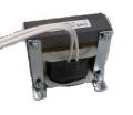
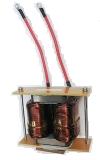
Line and Load Reactors are coils of wires wound on magnetic materials that are essentially inductors which oppose the rapid changes in current flow and reduce peak currents. These Reactors will also limit the starting current of a motor, reduce operating temperature of motors, reduce audible noise of motors, and improve efficiency of the overall system performance. Line Reactors are installed in series at the inputs of electronic motor controllers, and Load Reactors are installed in series between the motor controllers and the motor. The line and load reactors are designed the same way, with different values. Use of these Reactors can help in meeting the IEEE519 standards.
Applications of Line Reactors includes HVAC, pumping equipments, machine tools, elevators, UPS, Wind Generators, Electric Vehicle chargers, etc.
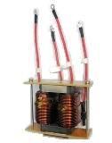
CWS offers both DC Line Reactors and AC Line Reactors. AC Line Reactors are for single phase and three phase lines.
How to Choose the Impedance of the Line Reactor.
1) 3% impedance line reactor will absorb spikes and surges and prevent unwanted tripping of drives in most applications. This is typically installed at the input of the drive controller.
2) 5% impedance load reactor should be chosen if harmonic content is severe or if the harmonics need to be reduced to meet IEEE519 requirements. This is typically installed at the input of the motor, after the drive controller.
It should be noted that connecting Reactors to a system will cause a voltage drop. This voltage drop will correspond to the current multiple by the impedance of the reactor.
A 5% Reactor will cause a voltage drop of 5% across the Reactor.