Mains Filters
Maximum power transfer occurs when source and load impedance are matched.
A power line filter is an inductor-capacitor network that aims to cause maximum mismatch between impedances, and therefore reduces the amount of EMI power to be transferred from the noise source onto the power line cable. Fig 12 shows a typical single-phase power line filter.
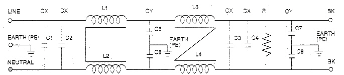
Figure 12
The inductors L1 and L2 are differential mode while L3/L4 are common mode. They are usually wound in current compensated fashion - on a toroidal core. This winding method allows flux due to differential mode currents and mains currents to cancel each other, while common mode currents will be added together. This gives a large inductance to common mode currents and insures that the inductor will not be saturated by the large magnetic flux produced by the mains current.
The capacitors placed between the phases, known as "X" class capacitors, must offer a high poise voltage rating and are used to attenuate differential mode interference.
The capacitor placed between the phase lines and the earth, known as "Y" class capacitors, must have a more stringent rating and are used to attenuate common mode interference (Table and Table 4).
|
Tab. 3 X-CAPACITORS
| Subgroup |
Pulse Peak Voltage in Operation |
Category of Installation to IEC 664 |
X1
X2
X3
|
>2.5kV
<4.0kV
<2.5kV
<1.2kV
|
III
-
II
-
|
|
The switching of class X capacitors in accordance with their application L-L, L-N, and in exceptional cases by applying additional safety measures, also to earth (PE).
Capacitors must meet the requirements of class X or Y (to VDE 0565, Part 1-1, EN 132400) if installed in filters generally designed for operation with mains a-c voltage.
Class X capacitors are assigned according to those peak voltages of pulses which interfere the a-c voltage mains during operation.
|
Tab. 4 Y-CAPACITORS
| Subgroup |
Type of Insulation By Passed According to IEC 536 |
Rate Voltage Range |
Peak Value of Impulse Voltage |
Y
Y2
Y3
Y4
|
insulation double or reinforced
base or additional insulation
base or additional insulation
base or additional insulation
|
<250V
>150V
<250V
>150V
<250V
<150V
|
8.0kV
5.0kV
Keine
2.5kV
|
|
The switching of Y capacitors is affected in accordance with their application to earth (PE).
Capacitors must meet the requirements of class X or Y (to VDE 0565, Part 1-1, EN 132400) if installed in filters generally designed for operation with mains a-c voltage.
Class Y capacitors are suited with which the failure of a capacitor could lead to dangerous electric shocks.
The value of the Y capacitor is restricted by the permissible leakage current allowed. The maximum leakage current is governed by standards and regulations and depends upon the type of equipment. The leakage current is given by:
lL = 2.Pi.U.f.c
Where "lL" is the leakage current; "U" the voltage across the capacitor; "f" the frequency of the mains voltage across the capacitor; and "c" the capacitance.
Mains filters should be mounted as close as possible to power entry so that high frequency interference does not bypass the filter. IEC inlet modules are ideally suited for this task.
To achieve higher attenuation or an increase in the effective working frequency range more complex filters than the one shown in Fig.12 can be made using more common mode or differential mode inductors or capacitors.
General Technical Data
All technical data is given at 25şC unless otherwise specified.
Current Ratings
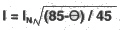
The current ratings given for each type is the maximum allowable current authorized by safety agencies at an ambient temperature of 40şC. Current at other temperatures is shown in the de rating curve, or can be ascertained by the formula:
Voltage Ratings
The maximum rated voltage of our filters is divided into two specifications, one for type testing and one for production testing. This is in accordance with guidelines laid down in various IEC recommendations. Type testing shall be a minimum of 2121DC for a minimum of 60 second between all terminals. However, the discharge resistor inside the filter shall be removed for testing according to IEC recommendations. All voltage tests shall not exceed 80% of the specified values.
Leakage Current
The leakage current to ground for each is given as a maximum value per phase, at 230V/50Hz.
Flammability Class
All filters in this catalogue are UL 94V-2 or UL 94V-0.
|
|
|
|
Need Power Magnetics? Then look no more! CWS ByteMark delivers the finest in surface mount and standard inductors like Power Transformers, Common Mode Chokes, Ceramic Chip Inductors and Wire Wound Chip Inductors. CWS ByteMark can supply all of your filtering needs as well, including EMI Filters, RFI Filters, LC Filter Inductors, and Common Mode Filters. From Transmission Line Transformers to power transformers, CWS ByteMark is the source to call!
We have direct crosses to all major manufacturers including Toko, CoilCraft, Coiltronics, Tokin, J.W. Miller, Arnold, Siemens, TDK, Gowanda, Taiyo Yuden and more! Call for details!
Your
comments and suggestions are important to us, please feel free to email
us at: sales@coilws.com
Call Us Toll Free:
1-800-377-3244
Copyright © 2001, Coilws.com, Inc
|